Fish Robotics, Biomimetics & Mechanical Design
Fish robotics is a major theme of research in our laboratory where we have developed a variety of robotic test platforms to examine fin and body kinematic and hydrodynamic function during locomotion. Robotic devices have the considerable advantage over studying live fish by allowing a variety of programmable motions that permit investigation of discrete components of naturally coupled movements. A key aspect of the mechanical design of these test platforms is that they are self-propelled and can swim against oncoming flow (and thus maintain station) in our recirculating flow tanks. An overview of our approach can be found in Lauder et al. (2007), and other papers relevant to this topic include Lauder and Madden (2006) and Tangorra et al. (2007).
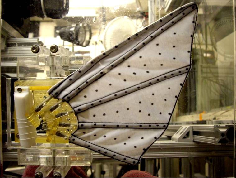
Latest generation robotic pectoral fin (Nov. 2007) showing the 5 fin rays embedded in the lycra fin membrane and the individual tendons that permit actuation of each fin ray. This fin was constructed by Dr. James Tangorra (MIT and Drexel University) as part of our collaborative research on fish pectoral fin robotics. We have measured the 3D kinematics of this fin and have conducted particle image velocimetry analyses of its hydrodynamic function along with simultaneous force measurements.

Design of our self-propelled dual flapping foil robot to study fish fin function. (A) Carriage that holds the dual foils, with the heave and pitch motors for each foil mounted above the flow tank on air bearings that allow horizontal translation in the X-direction with little friction. This design feature is critical to allowing self-propulsion. In this image, the two foils are suspended above the flow tank. (B) Close view of the two foils (NACA 0012 in cross-sectional shape); the foils are 6.85 cm in chord length (width) and 19 cm high. (C) Close view of the pitch and heave motors for one foil mounted on the carriage and air bearing system. See Lauder et al. (2007) for more details.

Schematic figure to illustrate our approach to the design of fishlike aquatic robot test platforms and the measurements that might be made from each design. (A) Robot is attached to a sting (a rod holding the robotic model vertically from the carriage above) and either fixed in place while forces are measured on the sting, or towed at a fixed velocity on a moving carriage. In either case, the robot is not self-propelled, but rather moves at an externally imposed speed. In this case, there need be no equality between thrust and drag forces, as it is not known if the robot is generating sufficient thrust to overcome drag. (B) Robot swims at a self-propelled time-averaged constant speed as a result of thrust generated by heave and pitch motions, and the mean thrust force per cycle must equal the mean drag force. The flow speed in the tank is adjusted to a value, Ueq, where the robot propels itself at a constant equilibrium X position, termed Xeq. The robot is free to move itself upstream and downstream on a low friction air bearing system. Once Xeq is determined for a particular heave and pitch motion pattern during self-propulsion, the robot can be fixed in position at Xeq to measure forces and torques while the same motion pattern and flow speed used for self-propulsion are imposed. This allows force measurement under conditions identical to self-propulsion, when thrust and drag forces must be equal. See Lauder et al. (2007) for more details.
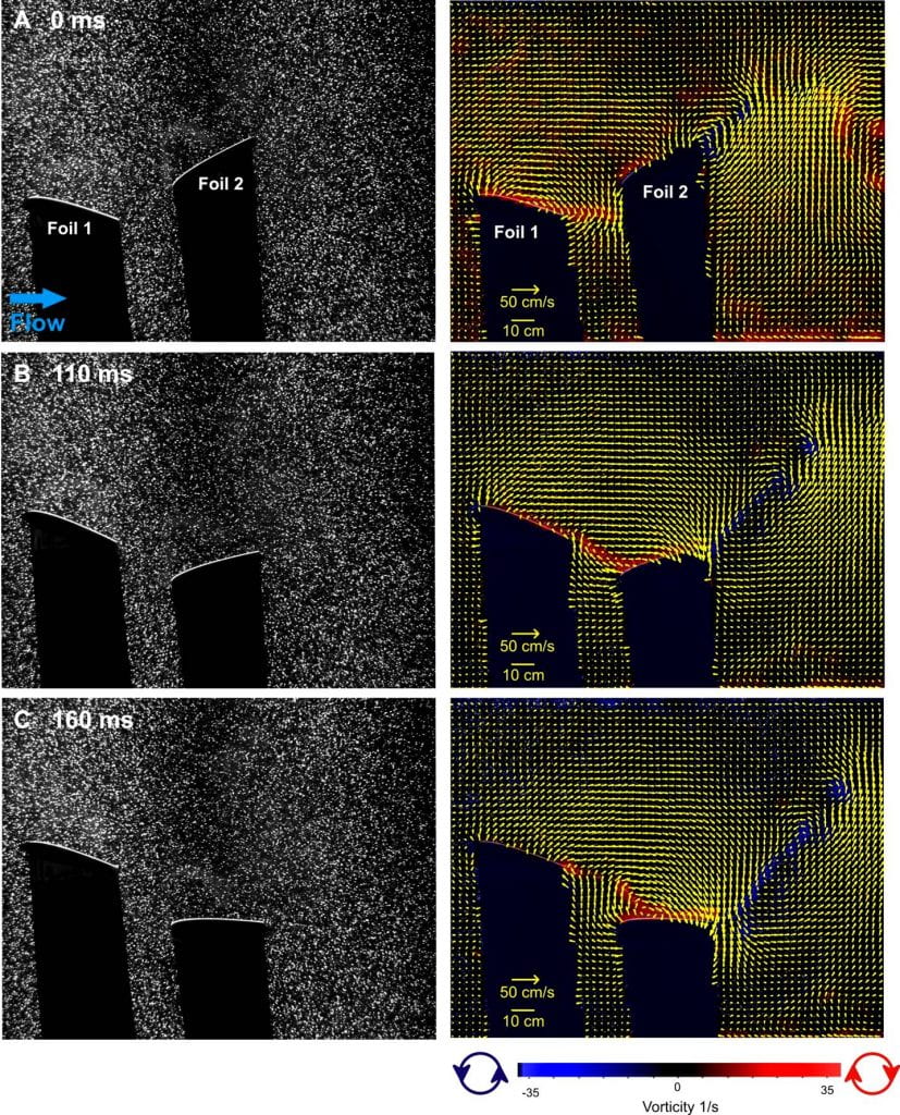
Hydrodynamics of our dual flapping foil robot, self-propelling at a speed of 53 cm/s. The distance between the foils is fixed at 0.5 chord lengths. The two foils have been programmed to move in sinusoidal motion with a 140° phase lag difference between them and a period of 588 ms. The front foil has a 20° pitch amplitude and a 2.5 cm heave distance, while the rear foil moves with 30° pitch amplitude and a 3.5 cm heave distance. These parameters are similar to those established in experimental and computational studies of bluegill sunfish dorsal and anal fins (Akhtar et al., 2007; Drucker and Lauder, 2001). The left panels show the foils and water illuminated by a laser light sheet from top to bottom in these images; the foils cast shadows toward the bottom. Video sample rate was 500 Hz. In the right panel these images are analyzed to show water flow velocities and vorticity around the two foils (vectors were not calculated in the fin shadows), as in the previous analysis of the sunfish dorsal and anal fins (Fig. 4). A distinct thrust wake is visible at 0 ms. Notice how vorticity from Foil 1 impacts Foil 2 as it moves in line with the first foil at 110 ms (B). An attached leading edge vortex is visible on Foil 2 at 160 ms, enhanced by incoming vorticity from Foil 1. Note also that water flow in the gap between the two foils is nearly orthogonal to free stream flow at 0 and 160 ms, similar to flow patterns observed between the dorsal fin and tail in sunfish (Fig. 4). Every other vector is shown for clarity in the right column; images on the left have been contrast-enhanced. See Lauder et al. (2007) for more details.
Hydrodynamics of a single, flexible, flapping foil self-propelling at a speed of 24 cm/s. The white arrow shows the heave motion (3.5 cm heave amplitude) of the rod that actuates the flexible foil, composed of a plastic sheet of the same dimensions as the foils in Fig. 9. Foil thickness is 0.32 mm, foil length=19 cm, foil height=6.8 cm, and the video sample rate is 250 Hz. The left panels show the flexible foil and water illuminated by a laser light sheet from top to bottom; the flexible foil casts a shadow toward the bottom of each image; these images have been contrast enhanced. Large yellow arrows in the left-hand panels show the direction of foil surface motion from one panel to the next. The actuating rod to which the foil is attached and the thin black foil itself have been enhanced by a white dot and line, respectively, for clarity. In the right panels these images are analyzed to quantify water flow velocities and vorticity around the flexible foil (vectors could not be calculated in the fin shadows), as in the previous analysis of two foil self-propulsion (Fig. 9). Note that an attached leading edge vortex (LEV) is visible at 0 ms as the foil leading edge nears the end of its downward motion and begins to move up. This attached LEV persists throughout the duration of the downstroke, until almost 930 ms (not shown). A distinct thrust wake is evident behind the flexible foil, with a strong side component. See Lauder et al. (2007) for more details.
See papers in the Download Reprints section for more on this topic, especially:

2006. Lauder, G.V. and P.G.A. Madden. Learning from fish: kinematics and experimental hydrodynamics for roboticists. International Journal of Automation and Computing 4:325-335.


2007. Lauder, G.V., Erik J. Anderson, James Tangorra and Peter G. A. Madden. Fish biorobotics: kinematics and hydronamics of self-propulsion.The Journal of Experimental Biology 210:2767-2780.


2007.Tangorra, J.L., S.N. Davidson, I.W. Hunter, P.G. Madden, G.V. Lauder, H. Dong, M. Bozkurttas and R. Mittal. The development of a biologically inspired propular for unmanned underwater vehicles. IEEE Journal of Oceanic Engineering 32(2): 533-550.

2010. Phelan, C., J. L. Tangorra, G. V. Lauder, and M. Hale. A biorobotic model of the sunfish pectoral fin for investigations of fin sensorimotor control. Bioinspiration and Biomimetics 5. DOI:10.1088/1748-3182/5/3/035003.

2010. Gottlieb, J.R., Tangorra, J.L., Esposito, C.J., and G.V. Lauder. A biologically derived pectoral fin for yaw turn maneuvers. Applied Bionic and Biomechanics 7:41-55.

2010. Tangorra, J.L., Lauder, G.V., Hunter, I.W., Mittal, R., Madden, P.G.A., and M. Bozkurttas. The effect of fin ray flexural rigidity on the propulsive forces generated by a biorobotic fish pectoral fin. Journal of Experimental Biology 213:4043-4054.

2011. Curet, O.M., Patankar, N.A., Lauder, G.V., and M.A. MacIver. Aquatic manoeuvering with counter-propagating waves: a novel locomotive strategy. Journal of the Royal Society Interface 8: 1041-1050. (Cover photo of this journal issue available.)

2011. Curet, O. M., Patankar, N. A., Lauder, G. V., and MacIver, M. A. Mechanical properties of a bio-inspired knifefish with an undulatory propulsor. Bioinspiration and Biomimetics 6: doi:10.1088/1748-3182/6/2/026004.

2011. Tangorra, J., Phelan, C., Esposito, C., and G.V. Lauder. Use of biorobotic models of highly deformable fins for studying the mechanics and control of fin forces in fishes. Integrative and Comparative Biology 51:176-189.

2011. Lauder, G.V., Lim, J., Shelton, R., Witt, C., Anderson, E.J., and Tangorra, J. Robotic models for studying undulatory locomotion in fishes. Marine Technology Society Journal 45: 41-55.

2012. Esposito, C.J., Tangorra, J.L., Flammang, B.E., and G.V. Lauder. A robotic fish caudal fin: effects of stiffness and motor program on locomotor performance. Journal of Experimental Biology 215: 56-67.